Most people have a rather simple understanding of how a nuclear reactor works. That is, they know that uranium atoms split into parts (i.e. they “fission”) in a reactor.
They also may have a very basic understanding of how a nuclear plant generates electricity. It does so in much the same way coal or gas-fired plants work: A heat source converts water into steam, which spins turbine blades. The turbine is attached to a generator by a rotating shaft; as the latter spins, the generator creates electricity.
Following is an attempt to make the basic concepts associated with the complex workings of a water-cooled nuclear reactor more well understood.
Nuclear Fuel
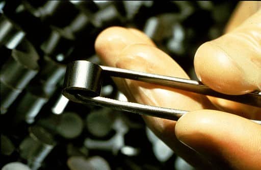
The fuel for a water-cooled nuclear reactor consists of uranium oxide pellets (Figure 1) which are stacked inside a long cylindrical fuel rod (Figure 2).
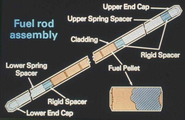
Fuel rods are configured into fuel assemblies (Figure 3) using grid spacers such that cooling water is able to flow around the fuel rods to remove heat produced by nuclear fission during reactor operation. The fuel assemblies are arranged in a cylindrical configuration inside a large, open-top steel vessel called a core barrel, to form the reactor core (Figure 4).
Nuclear Reactor Pressure Vessel
The reactor core is located inside an even bigger steel vessel called the reactor pressure vessel, with a removeable upper head and piping nozzles to accommodate the flow of cooling water through the reactor core (Figure 5).
The reactor control rods that control the fission chain reaction in the reactor core are connected to control rod drive mechanisms in the upper vessel head for a pressurized-water reactor, or in the bottom of the reactor vessel for a boiling-water reactor.
Nuclear Steam Supply System
The primary cooling system of a nuclear power plant is known as the nuclear steam supply system (NSSS). The secondary system that generates electricity is known as the balance of the plant (BOP).
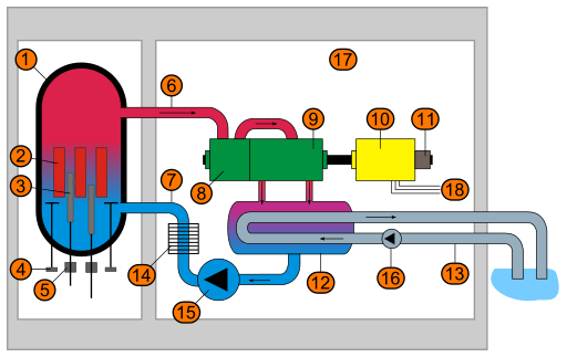
The nuclear steam supply system for the pressurized-water reactor (PWR) illustrated in Figure 6 consists of a reactor pressure vessel, a pressurizer to control primary system pressure, and two or more cooling loops, each containing a steam generator and a reactor coolant pump.
The entire PWR NSSS is contained within a steel-reinforced concrete structure known as the containment building. PWRs operate at a primary system pressure of greater than 2,000 psia (pounds per square inch absolute, or “absolute pressure”) to ensure that the primary coolant water remains subcooled as it removes heat from the reactor core. The primary coolant water transfers its heat to the lower-pressure secondary coolant water in the steam generator, thereby boiling the secondary side water to generate steam.
The boiling-water reactor (BWR) NSSS (Figure 7) consists of a reactor pressure vessel and two or more coolant recirculation loops. Similar to the PWR NSSS, the entire BWR NSSS is located within a containment structure. BWRs operate at a pressure above 1,000 psia. The water entering the reactor vessel is converted to steam as it removes heat from the reactor core. The steam passes through steam separator/dryers in the top of the reactor vessel prior to exiting the vessel.
Reactor Operation Is All About Neutrons
So how does one operate a water-cooled nuclear reactor? Control rods are used to control a nuclear fuel’s rate of fission. An overly-simplistic expectation would be that one ever so slowly removes control rods from the reactor core until a self-sustaining fission chain reaction is achieved. If only life were that simple. The reality is much more complicated.
It’s all about neutrons, those neutral particles in the atomic nucleus that cause uranium atoms to fission. It’s about how they are generated and how the reactor neutron population is controlled through proper reactor design and operation to produce electrical power safely.
Source Neutrons
First, a source of neutrons is necessary to initiate the fission chain reaction in a nuclear reactor. Therefore, a neutron source (e.g., plutonium-beryllium or radium-beryllium) must be inserted into the reactor core prior to reactor startup with un-irradiated fuel or when restarting a reactor following a shutdown. Neutron sources in a PWR are inserted into the core via control-rod guide tubes in the upper reactor vessel head. In a BWR, sources are inserted via in-core instrumentation guide tubes penetrating the bottom of the reactor vessel. Once a self-sustaining fission chain reaction is achieved the neutron sources are removed from the core.
Neutron Balance
Next, one must be able to achieve and sustain a stable neutron population to produce the desired reactor power. The neutron population is characterized by a parameter called the neutron multiplication factor (k), which is the ratio of neutrons produced by fission in one generation to the number of neutrons lost through absorption (including those producing fission) and leakage from the reactor core in the preceding generation. A critical system exists when an average of one neutron from each fission causes another fission. Under such conditions, the multiplication factor is unity (1). If the multiplication factor is less than 1 (a subcritical system), then the reactor is incapable of a self-sustaining fission chain reaction. When k is not equal to exactly 1 the neutron population will change, causing a change in reactor power level (i.e., energy generation rate).
Changes in the Neutron Balance
Power reactors must also have the capability to adjust the neutron balance in order to 1) increase reactor power, 2) reduce power or shut the reactor down, and 3) compensate for fuel depletion over time. This can only be accomplished by controlling the fission reaction rate in the fuel, which is a function of the mean neutron generation time; that is, the time required for neutrons from one generation to cause fissions that produce the next generation of neutrons.
The mean generation time for prompt fission neutrons, which make up 99.35 percent of total fission neutrons in water-cooled reactors, is approximately 100 microseconds. The significance of this extremely short time period is that for a positive change in a stable neutron balance the neutron population would increase by a factor of approximately 20,000 in one second (two neutrons produced per fission every 100 microseconds). This is much too fast for operator or automatic mechanical system action to control the resulting increase in reactor power.
Delayed Neutrons
Fortunately, the generation of a small fraction of fission neutrons (0.65 percent) is delayed. Such neutrons come about from the beta particle radioactive decay of certain fission fragments, with a neutron being expelled from the daughter nucleus. The time delay for generation of these neutrons (the longest being about 56 seconds) significantly increases the overall mean neutron-generation time, making a very significant contribution to the time-dependent behavior of the reactor neutron population and thus making power reactor control possible. In fact, the delayed neutron fraction (denoted by the symbol β) of 0.0065 is the single most important parameter for achieving and maintaining a sustained, controlled fission chain reaction in the reactor fuel.
Neutron Multiplication and System Reactivity
Because k=1 always implies reactor criticality, k–1 represents the excess neutron multiplication with respect to the critical condition. The fractional excess multiplication, represented by (k–1)/k (or Δk/k), defines the system reactivity (ρ). Changes in system reactivity, which can be either positive (neutron population increase) or negative (neutron population decrease), occur as the result of variations in system physical parameters (e.g., control-rod movement). Reactors are designed to ensure that the percent change in a positive reactivity increase is much smaller than the delayed neutron fraction (0.65 percent) so that the associated increase in reactor power is accomplished in a controlled manner. (Note that all power reactor cores have built-in excess reactivity [the uranium fuel] to allow for 18 to 24 months of continuous operation.)
Delayed Neutrons and Reactor Criticality
Nuclear reactors are designed to “go critical” (k=1) with the aid of delayed neutrons so that the fission rate at criticality (i.e., the change in reactor power) can be controlled. Reactors also rely on delayed neutrons to hold the fission reaction rate reasonably constant for steady-state power operation. An operating reactor actually fluctuates between being slightly subcritical (k<1) and slightly delayed-supercritical (k>1), but must always remain below prompt critical (a condition in which the reactor is critical on prompt neutrons alone).
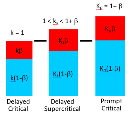
Figure 8 illustrates the contributions of the delayed neutron fraction (β) and the prompt neutron fraction (1-β) for delayed critical (k=1), delayed supercritical (1<ks<1+β), and prompt critical (kp=1+β) reactor core conditions. As stated previously, reactors are designed to ensure that the percent change in a positive reactivity increase is much smaller than the delayed neutron fraction (β) so that they cannot go prompt critical.
Practical System Criticality Control
Although understanding the concepts of neutron multiplication and system reactivity may be necessary to understanding how a reactor operates, these characteristics of real-time neutron behavior in a reactor cannot be measured directly. What the reactor operator relies upon is a measurable parameter called the reactor period.
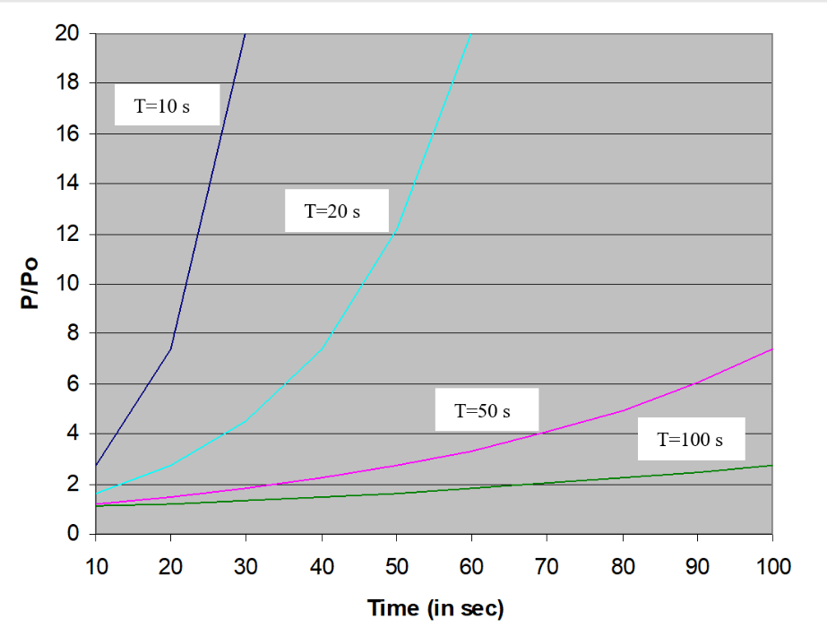
Most reactor power level changes are initiated by control rod movement. Control-rod withdrawal from the reactor core exposes more reactor fuel to the fission process, resulting in an increase in the neutron population (a positive reactivity change) and an increased rate of fission (heat generation rate). Control rod insertion, on the other hand, results in a negative reactivity change and a decreased heat generation rate in the reactor fuel. Reactor power level changes in a time-dependent manner according to the equation
P=Poet/T
where Po is the initial reactor power, t is the time of the reactor power transient (or change in the fission rate) in seconds, and T is the reactor period in seconds. The reactor period is the time required for reactor power to change by factor of e (i.e., a factor of 2.718) and can be either positive (for a power increase) or negative (for a power decrease). Figure 9 illustrates how the power increases as a function of time for reactor periods of 10, 20, 50, and 100 seconds.
Proper integration of composition and geometry of nuclear fuel, reactor core materials, thermal-hydraulics, and reactivity control features in reactor design assures that 1) planned and inadvertent reactivity changes are small (much less than the delayed neutron fraction of 0.65 percent, thereby assuring a sufficiently long reactor period) and 2) reactivity feedback mechanisms (e.g., fuel temperature, moderator temperature, moderator density) are negative and operate on short time scales (Figure 10).
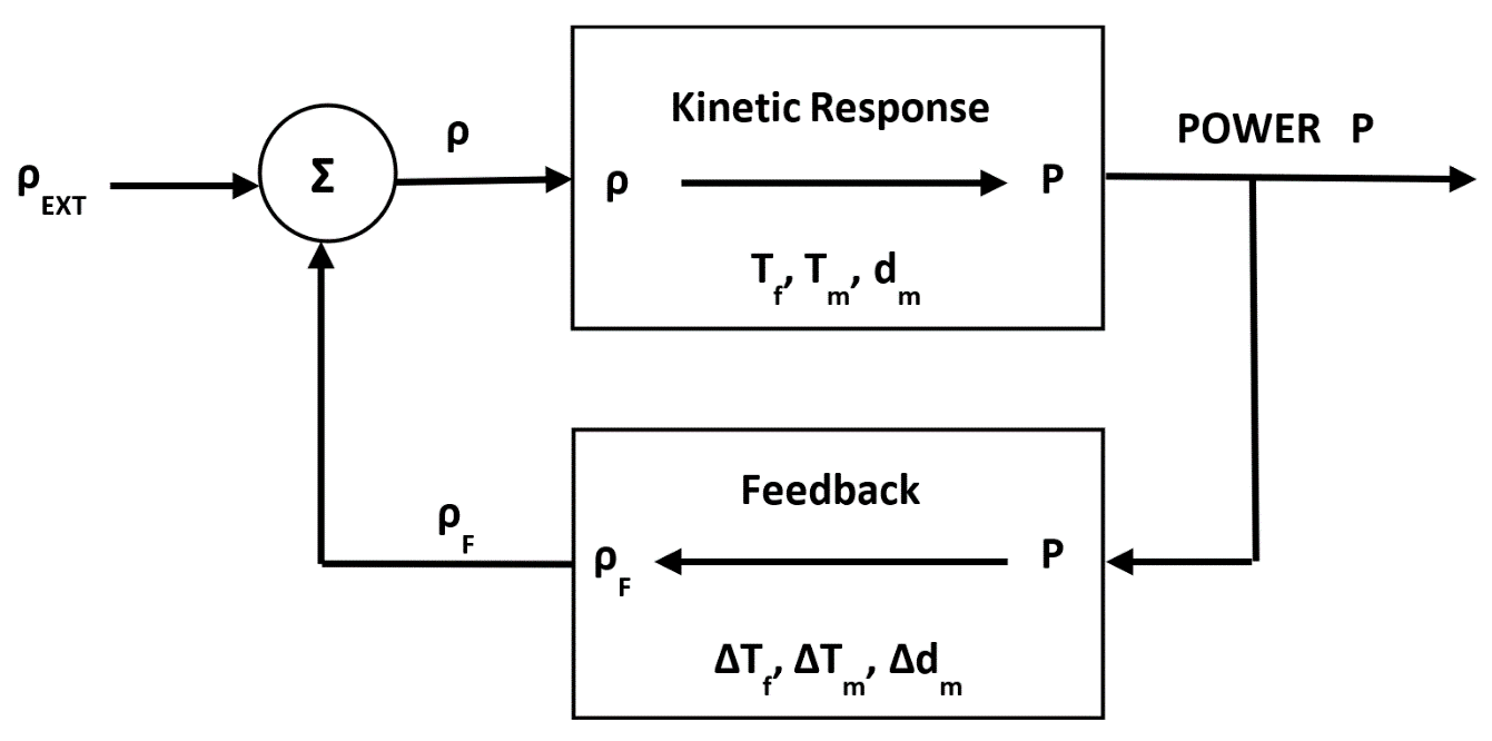
Reactivity changes in a reactor are always followed by feedback responses as shown in Figure 10. A small positive reactivity insertion (e.g., control-rod withdrawal) produces an initial prompt jump in power, due to the increase in the prompt neutron population, and then a power increase on an asymptotic reactor period. When the power increase begins to produce significant temperature increases, the negative feedback mechanisms (fuel temperature, moderator temperature, and moderator density) modify the reactor behavior. That is, the negative feedback continues until the system stabilizes at some time, t, when the sum of the positive reactivity insertion (ρEXT) and the negative feedback reactivity (ρF) are equal (i.e., ρ=0 in Figure 10). The system thus experiences a gradual lengthening of the reactor period during which there is a leveling off of reactor power and temperatures above their initial values.
Typical positive reactivity changes in nuclear reactors are significantly less than 0.1 percent. This assures a sufficiently long reactor period to control the associated reactivity-induced power increase with feedback alone. As long as reactor feedback occurs on a time scale shorter than the reactor period, power changes take place in an orderly and controlled fashion without the need for operator intervention. Sequential control-rod withdrawals to achieve stabilized intermediate power levels is how reactors get from initial criticality to 100 percent power operation. Similarly, orderly reactor shutdown is achieved by sequential control rod insertions.
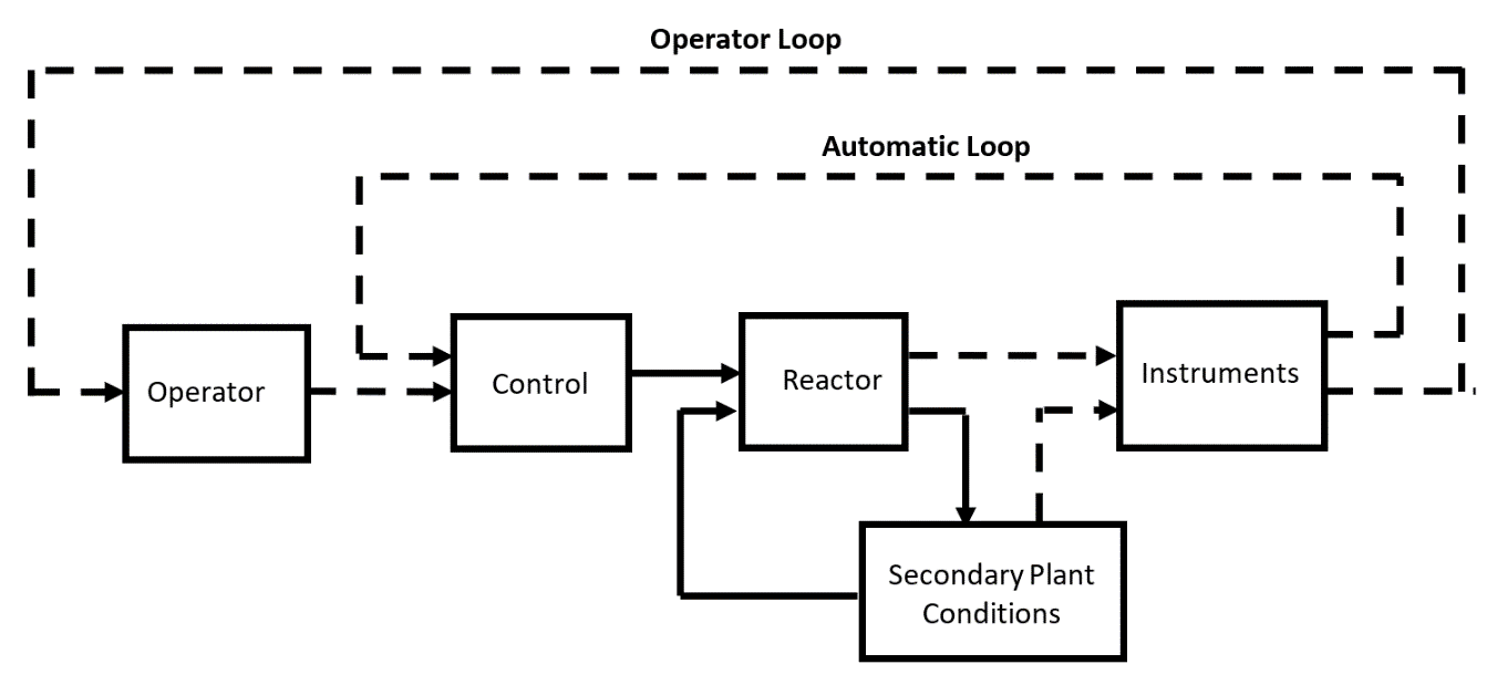
Finally, in-core instrumentation, which can detect changes in the reactor core neutron population, provides signals to reactor operators as well as to automatic control and safety systems (Figure 11). Automatic control mechanisms compensate for transient changes in reactivity, such as might result from minor variations in coolant flow, as well as steady changes due to fuel depletion and accumulation of fission product poisons (i.e., neutron-absorbing isotopes such as xenon-135 and samarium-149). Automatic safety mechanisms terminate abnormal transients or operational upset conditions that exceed the control capability of reactor operators and automatic control mechanisms.
Related articles:
Dispelling Irrational Fear of Radiation
Understanding Radiation Risks and Benefits
The Dynamic World of Radioactive Decay